


Several Common Damage Phenomena and Failure Reasons of Supporting Wheel of Excavator
The track roller of excavator bears the quality and working load of excavator itself. The attributes of supporting wheel are the important criteria to measure the quality of excavator. This paper analyses the attributes of supporting wheel and its damage and causes.
1.Attributes of the track roller of excavators
(1) Structure
The structure of the supporting wheel is shown in Figure 1. The outer cover 2 and the inner cover 8 at both ends of the main shaft 7 of the supporting wheel are fixed at the lower part of the crawler rack of the excavator. After fixing the outer cover 2 and the inner cover 8, not only the axial movement of the main shaft 7 can be prevented, but also the rotation of the main shaft 7 can be prevented. The flanges on both sides of the wheel body 5 can clamp the caterpillar chain rail to prevent derailment of the caterpillar and ensure that the excavator travels along the track.
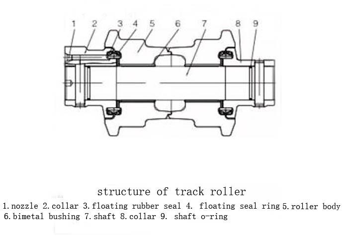
The inner part of the outer cover 2 and the inner cover 8 are respectively provided with a pair of floating ring 4 and floating apron 3. After the outer cover 2 and the inner cover 8 are fixed, the floating APRON 3 and the floating apron 4 are pressed together. The contact surfaces of the two floating rings 4 are smooth and hard, forming a sealing surface. When the wheel rotates, two floating rings 4 rotate relative to each other, forming a floating seal. O-ring 9 is used for sealing between spindle 7 and outer cover 2 and inner cover 8. Floating seal and O-ring 9 can prevent oil leakage in the supporting wheel and prevent mud water from immersing into the inside of the supporting wheel. The oil hole in the screw plug 1 is used to add lubricating oil to the inner part of the supporting wheel.
(2) Force condition
The wheel body of the supporting wheel of the excavator is supported upward by the caterpillar track, and the two ends of the main shaft bear the gravity of the excavator, as shown in Figure 2.
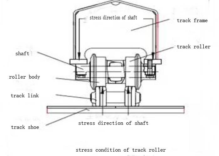
The gravity of excavator is transmitted to the main shaft 7 through crawler rack, outer cover 2 and inner cover 8, to the sleeve 6 and wheel body 5 through the main shaft 7, and then to the chain rail and track board through the wheel body 5 (see Fig. 1). When excavators work in uneven ground, they are easy to cause the inclination of caterpillar plate and the inclination of chain rail. When the excavator is steering, there will be axial channeling power between the spindle and the wheel body. Because of the complex stress of the supporting wheel, its structure must be reasonable, and the spindle, wheel body and bushing need to have relatively high strength, toughness, wear resistance and sealing.
(3) Technical requirements
The spindle is made of 50Mn high quality carbon structural steel with C content of 0.48%~0.56%, Si content of 0.17%~0.37%, Mn content of 0.7%~1.0%, S content of less than 0.035%, P content of less than 0.035%, Cr content of less than 0.25%, Ni content of less than 0.30%, and Cu content of less than 0.25%. Among them, Mn is an important element in alloy steel, which can improve the forging and plasticity of steel and ensure that the material has sufficient toughness and wear resistance. After heat treatment, 50Mn steel has higher strength and hardness, excellent hardenability, deeper hardening layer, finer pearlite structure and better mechanical properties.
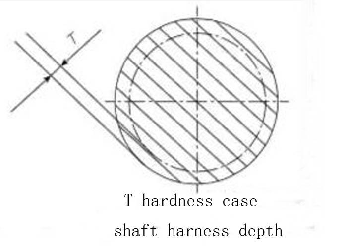
The design standard of spindle requires that the depth of hardening layer T is 2 ~ 7mm and the hardness is 50 ~ 62HRC, as shown in Fig. 3.
The track surface of wheel body supporting wheel bears frequent impact loads and is prone to extrusion deformation, which makes the track surface of wheel body extend into a conical shape. In order to improve the stress condition, we have lengthened the length of the track surface of the wheel body and designed the transition between the track surface and the wheel waist as an incline to improve the support capacity of the track surface. The shadow part shown in Figure 4 is the extended track surface and the transition slope. In order to improve the wear resistance of the wheel body of the supporting wheel, the material of the wheel body is 40Mn2 alloy structural steel. C content is 0.37%~0.44%, Si content is 0.17%~0.37%, Mn content is 1.4%~1.8%, P content is less than 0.030%, S content is less than 0.030%.

The wheel body is formed by forging. After forming, the wheel blank is conditioned and the hardness reaches 26-32 HRC, so as to maintain the high strength, plasticity, toughness and comprehensive mechanical properties of the wheel body. The surface of the wheel body is quenched to improve the hardness and wear resistance of the track surface of the supporting wheel. Quenching hardness is 50 ~ 58HRC, hardening depth is 6 ~ 12mm, so the hardness of track surface is close to that of chain rail joint (48 ~ 58HRC).
The groove size and surface roughness of O-ring should meet the design requirements. The matching surface should be chamfered and burrs and sharp edges should be cleared.
Buoyancy sealing ring and O-ring should be made of high quality NBR. The inner diameter, line diameter, elasticity, hardness (Shao's) and surface finish should meet the standard. Before assembly, they should be inspected one by one according to the above items before they can be put into assembly.
If the floating ring is not enclosed in the groove of the floating ring or is not connected with the floating ring, the pressure on the floating ring will be uneven. The uneven pressure will cause worsening of the local edge surface when the floating ring rotates, which will lead to oil leakage of the floating ring. If the edge of O-ring is cut off, half of the ring is clamped outside the ring groove, or is twisted when the ring groove is loaded, the sealing performance or service life of O-ring will be reduced. Sometimes, if the pressure of air tightness inspection does not reach a certain value, the leakage will not occur after oil injection. But after a certain time of excavator operation, the friction temperature of each component of the supporting wheel and the pressure of the inner chamber will rise to a certain value, the leakage will occur. If it continues to be used after leaking, serious oil leakage will occur in floating oil seal.
The clearance between the main shaft of the clearance supporting wheel and the sleeve on the wheel body is 0.2-0.4 mm. There should be no blocking phenomenon when rotating. The sealing performance is good and there is no oil leakage.
Lubrication should use the oiler to add gear oil to the supporting wheel, and if necessary, properly improve the viscosity of the lubricating oil. Before filling the gear oil, the gear oil that has failed should be exhausted, and then the new gear oil should be added to the plug hole until the oil is out. When lubricating oil is added, screw down the shaft end screw, put the end of the injector nozzle on the shoulder of the oil passage, and inject oil into the oil passage. When installing the oil plug, it is necessary to use a torque wrench to control the tightening moment of the oil plug in the range of 157-255N M.
2. Cause Analysis of Damage of Excavator Load Wheel
Taking a 20t excavator of a manufacturer as an example, this paper analyses the reasons for the damage of its supporting wheels. We inspected some damaged supporting wheels of the excavator and found that the main faults were spindle, wheel body damage and oil leakage. Among them, the main axle of the heavily damaged supporting wheel appears to hold the axle, which makes the whole supporting wheel unable to rotate. Now the analysis is carried out separately.
(1) Shaft damage
When the material is not up to standard, we use spectrometer to detect the content of elements in the damaged spindle of the supporting wheel. The measured content of Mn element is 0.59%, which is quite different from the standard content (0.7%~1.0%). This seriously affects the mechanical properties of the spindle.
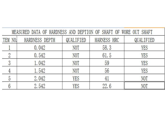
The surface hardness and hardening depth of damaged spindle are measured by unqualified heat treatment, as shown in Table 1. The test data show that the hardness of the spindle surface and the depth of the hardened layer can not meet the design requirements, which seriously affects the strength, stiffness and wear resistance of the spindle.
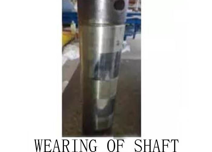
Severe wear was found by testing that the bending of the spindle, the diameter of the spindle and the mating part of the sleeve were worn seriously, as shown in Fig. 5. After measurement, the clearance between the spindle and the sleeve is more than 0.3 mm (the clearance should be less than 0.2 mm), and the spindle and sleeve need to be updated.
(2) Wheel damage
Check the damaged wheel body of the supporting wheel and find out the deformation, cracking and falling of the track surface of the wheel body. Fig. 6 shows that the raceway surface of the supporting wheel extends to a conical shape after being impacted.
The serious wear of wheel body is mainly manifested in track surface, guide cam flange and axle sleeve seat hole. This is because excavators often work in sand, mud and gravel sites, and a large number of abrasives enter the rail surface and chain rail of the supporting wheel, forming a strong abrasive wear, and these gravels produce large extrusion stress between the rail surface and the flange and the track link, forming a lot of micro-extrusion deformation and dry friction. These dry friction have both rolling friction and sliding friction, which results in serious wear of wheel track surface and reduces the rigidity and strength of wheel body. The derailment of the supporting wheel is easy to occur after the flange is severely worn.
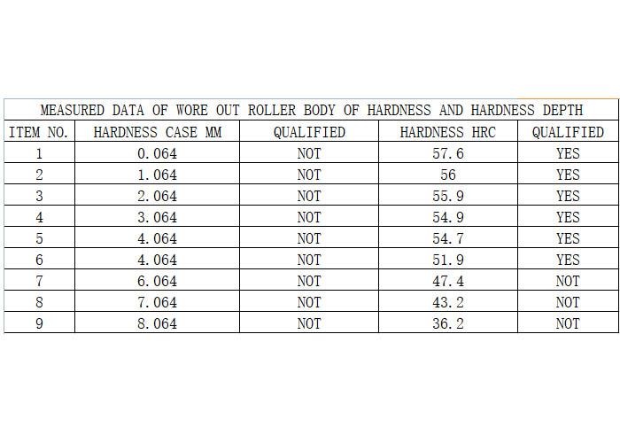
The measured results are shown in Table 2. The measured data show that the quenched hardness and depth of hardened layer on the surface of the wheel body do not meet the design requirements.
Anatomy of the wheel with defective material reveals that there are cracks in it, as shown in Figure 7. This indicates that the forging process of wheel blank is unqualified, and the forging process should be improved to prevent the coarse grains and abnormal structure.

(3) Oil leakage
The dimension of O-ring sealing groove (groove width, groove depth, O-groove roundness, etc.) of the main shaft of the supporting wheel are all within the design tolerance range, which meets the technical requirements. Detection of floating seal apron, O-ring line diameter and internal diameter of the size of excessive, surface damage. The reason for the damage is that the material of the sealing ring is not qualified, which is manifested in expansion deformation, loss of elasticity, early aging, hardness (Shao's) does not meet the design requirements after contact with lubricating oil, and oil leakage is caused by improper sealing. There are two reasons for oil leakage of supporting wheels: one is that the supporting wheels are immersed in water for a long time during excavator operation, resulting in corrosion of floating ring and O-ring groove; the other is that construction in mud water in winter results in freezing failure of floating ring.


